配置OSPF基本功能示例
以下是华为HUAWEI CE8850-64CQ-EI交换机的一个osfp配置实例,供参考
组网需求
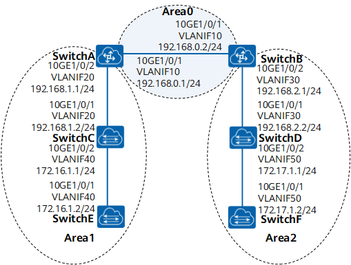
如图1所示,所有的交换机都运行OSPF,并将整个自治系统划分为3个区域,其中SwitchA和SwitchB作为ABR来转发区域之间的路由。
配置完成后,每台交换机都应学到自治系统内的到所有网段的路由。
图1 配置OSPF基本功能组网图
配置思路
采用如下的思路配置OSPF基本功能:
- 在各交换机上使能OSPF。
- 指定不同区域内的网段。
操作步骤
-
配置各接口的IP地址(略)
-
配置OSPF基本功能
# 配置SwitchA。
system-view [~HUAWEI] sysname SwitchA[*HUAWEI] commit[~SwitchA] router id 10.1.1.1[*SwitchA] ospf 1[*SwitchA-ospf-1] area 0[*SwitchA-ospf-1-area-0.0.0.0] network 192.168.0.0 0.0.0.255[*SwitchA-ospf-1-area-0.0.0.0] quit[*SwitchA-ospf-1] area 1[*SwitchA-ospf-1-area-0.0.0.1] network 192.168.1.0 0.0.0.255[*SwitchA-ospf-1-area-0.0.0.1] quit[*SwitchA-ospf-1] commit[~SwitchA-ospf-1] quit# 配置SwitchB。
system-view [~HUAWEI] sysname SwitchB[*HUAWEI] commit[~SwitchB] router id 10.2.2.2[*SwitchB] ospf 1[*SwitchB-ospf-1] area 0[*SwitchB-ospf-1-area-0.0.0.0] network 192.168.0.0 0.0.0.255[*SwitchB-ospf-1-area-0.0.0.0] quit[*SwitchB-ospf-1] area 2[*SwitchB-ospf-1-area-0.0.0.2] network 192.168.2.0 0.0.0.255[*SwitchB-ospf-1-area-0.0.0.2] quit[*SwitchB-ospf-1] commit[~SwitchB-ospf-1] quit# 配置SwitchC。
system-view [~HUAWEI] sysname SwitchC[*HUAWEI] commit[~SwitchC] router id 10.3.3.3[*SwitchC] ospf 1[*SwitchC-ospf-1] area 1[*SwitchC-ospf-1-area-0.0.0.1] network 192.168.1.0 0.0.0.255[*SwitchC-ospf-1-area-0.0.0.1] network 172.16.1.0 0.0.0.255[*SwitchC-ospf-1-area-0.0.0.1] commit[~SwitchC-ospf-1-area-0.0.0.1] quit[~SwitchC-ospf-1] quit# 配置SwitchD。
system-view [~HUAWEI] sysname SwitchD[*HUAWEI] commit[~SwitchD] router id 10.4.4.4[*SwitchD] ospf 1[*SwitchD-ospf-1] area 2[*SwitchD-ospf-1-area-0.0.0.2] network 192.168.2.0 0.0.0.255[*SwitchD-ospf-1-area-0.0.0.2] network 172.17.1.0 0.0.0.255[*SwitchD-ospf-1-area-0.0.0.2] commit[~SwitchD-ospf-1-area-0.0.0.2] quit[~SwitchD-ospf-1] quit# 配置SwitchE。
system-view [~HUAWEI] sysname SwitchE[*HUAWEI] commit[~SwitchE] router id 10.5.5.5[*SwitchE] ospf 1[*SwitchE-ospf-1] area 1[*SwitchE-ospf-1-area-0.0.0.1] network 172.16.1.0 0.0.0.255[*SwitchE-ospf-1-area-0.0.0.1] commit[~SwitchE-ospf-1-area-0.0.0.1] quit[~SwitchE-ospf-1] quit# 配置SwitchF。
system-view [~HUAWEI] sysname SwitchF[*HUAWEI] commit[~SwitchF] router id 10.6.6.6[*SwitchF] ospf 1[*SwitchF-ospf-1] area 2[*SwitchF-ospf-1-area-0.0.0.2] network 172.17.1.0 0.0.0.255[*SwitchF-ospf-1-area-0.0.0.2] commit[~SwitchF-ospf-1-area-0.0.0.2] quit[~SwitchF-ospf-1] quit -
验证配置结果
# 查看SwitchA的OSPF邻居。
[~SwitchA] display ospf peerOSPF Process 1 with Router ID 10.1.1.1 Area 0.0.0.0 interface 192.168.0.1(Vlanif10)'s neighbors Router ID: 10.2.2.2 Address : 192.168.0.2 State : Full Mode : Nbr is Master Priority: 1 DR : 192.168.0.2 BDR : 192.168.0.1 MTU : 0 Dead timer due (in seconds) : 36 Retrans timer interval : 5 Neighbor up time : 02h29m06s Authentication Sequence : 0 Area 0.0.0.1 interface 192.168.1.1(Vlanif20)'s neighbors Router ID: 10.3.3.3 Address : 192.168.1.2 State : Full Mode : Nbr is Master Priority: 1 DR : 192.168.1.2 BDR : 192.168.1.1 MTU : 0 Dead timer due (in seconds) : 33 Retrans timer interval : 5 Neighbor up time : 02h28m52s Authentication Sequence : 0# 显示SwitchA的OSPF路由信息。
[~SwitchA] display ospf routingOSPF Process 1 with Router ID 10.1.1.1 Routing for Network -------------------------------------------------------------------------------- Destination Cost Type NextHop AdvRouter Area 172.16.1.0/24 2 Transit 192.168.1.2 10.3.3.3 0.0.0.1 172.17.1.0/24 3 Inter-area 192.168.0.2 10.2.2.2 0.0.0.0 192.168.0.0/24 1 Direct 192.168.0.1 10.1.1.1 0.0.0.0 192.168.1.0/24 1 Direct 192.168.1.1 10.1.1.1 0.0.0.1 192.168.2.0/24 2 Inter-area 192.168.0.2 10.2.2.2 0.0.0.0 Total Nets: 5 Intra Area: 3 Inter Area: 2 ASE: 0 NSSA: 0# 显示SwitchA的LSDB。
[~SwitchA] display ospf lsdbOSPF Process 1 with Router ID 10.1.1.1 Link State Database Area: 0.0.0.0 ---------------------------------------------------------------------------- Type LinkState ID AdvRouter Age Len Sequence Metric Router 10.1.1.1 10.1.1.1 93 48 80000004 1 Router 10.2.2.2 10.2.2.2 92 48 80000004 1 Sum-Net 172.16.1.0 10.1.1.1 1287 28 80000002 2 Sum-Net 192.168.1.0 10.1.1.1 1716 28 80000001 1 Sum-Net 172.17.1.0 10.2.2.2 1336 28 80000001 2 Sum-Net 192.168.2.0 10.2.2.2 87 28 80000002 1 Area: 0.0.0.1 ---------------------------------------------------------------------------- Type LinkState ID AdvRouter Age Len Sequence Metric Router 10.1.1.1 10.1.1.1 1420 48 80000002 1 Router 10.3.3.3 10.3.3.3 1294 60 80000003 1 Router 10.5.5.5 10.5.5.5 1296 36 80000002 1 Network 172.16.1.1 10.3.3.3 1294 32 80000001 0 Sum-Net 172.17.1.0 10.1.1.1 1325 28 80000001 3 Sum-Net 192.168.0.0 10.1.1.1 1717 28 80000001 1 Sum-Net 192.168.2.0 10.1.1.1 1717 28 80000001 2# 查看SwitchD的路由表,并使用Ping进行测试连通性。
[~SwitchD] display ospf routingOSPF Process 1 with Router ID 10.4.4.4 Routing for Network -------------------------------------------------------------------------------- Destination Cost Type NextHop AdvRouter Area 172.16.1.0/24 4 Inter-area 192.168.2.1 10.2.2.2 0.0.0.2 172.17.1.0/24 1 Direct 172.17.1.1 10.4.4.4 0.0.0.2 192.168.0.0/24 2 Inter-area 192.168.2.1 10.2.2.2 0.0.0.2 192.168.1.0/24 3 Inter-area 192.168.2.1 10.2.2.2 0.0.0.2 192.168.2.0/24 1 Direct 192.168.2.2 10.4.4.4 0.0.0.2 Total Nets: 5 Intra Area: 2 Inter Area: 3 ASE: 0 NSSA: 0[~SwitchD] ping 172.16.1.1PING 172.16.1.1: 56 data bytes, press CTRL_C to breakReply from 172.16.1.1: bytes=56 Sequence=1 ttl=253 time=62 msReply from 172.16.1.1: bytes=56 Sequence=2 ttl=253 time=16 msReply from 172.16.1.1: bytes=56 Sequence=3 ttl=253 time=62 msReply from 172.16.1.1: bytes=56 Sequence=4 ttl=253 time=94 msReply from 172.16.1.1: bytes=56 Sequence=5 ttl=253 time=63 ms--- 172.16.1.1 ping statistics ---5 packet(s) transmitted5 packet(s) received0.00% packet lossround-trip min/avg/max = 16/59/94 ms
配置文件
-
SwitchA的配置文件
# sysname SwitchA # vlan batch 10 20 # router id 10.1.1.1 # interface Vlanif10 ip address 192.168.0.1 255.255.255.0 # interface Vlanif20 ip address 192.168.1.1 255.255.255.0 # interface 10GE1/0/1 port link-type trunk port trunk allow-pass vlan 10 # interface 10GE1/0/2 port link-type trunk port trunk allow-pass vlan 20 # ospf 1 area 0.0.0.0 network 192.168.0.0 0.0.0.255 area 0.0.0.1 network 192.168.1.0 0.0.0.255 # return -
SwitchB的配置文件
# sysname SwitchB # vlan batch 10 30 # router id 10.2.2.2 # interface Vlanif10 ip address 192.168.0.2 255.255.255.0 # interface Vlanif30 ip address 192.168.2.1 255.255.255.0 # interface 10GE1/0/1 port link-type trunk port trunk allow-pass vlan 10 # interface 10GE1/0/2 port link-type trunk port trunk allow-pass vlan 30 # ospf 1 area 0.0.0.0 network 192.168.0.0 0.0.0.255 area 0.0.0.2 network 192.168.2.0 0.0.0.255 # return -
SwitchC的配置文件
# sysname SwitchC # vlan batch 20 40 # router id 10.3.3.3 # interface Vlanif20 ip address 192.168.1.2 255.255.255.0 # interface Vlanif40 ip address 172.16.1.1 255.255.255.0 # interface 10GE1/0/1 port link-type trunk port trunk allow-pass vlan 20 # interface 10GE1/0/2 port link-type trunk port trunk allow-pass vlan 40 # ospf 1 area 0.0.0.1 network 192.168.1.0 0.0.0.255 network 172.16.1.0 0.0.0.255 # return -
SwitchD的配置文件
# sysname SwitchD # vlan batch 30 50 # router id 10.4.4.4 # interface Vlanif30 ip address 192.168.2.2 255.255.255.0 # interface Vlanif50 ip address 172.17.1.1 255.255.255.0 # interface 10GE1/0/1 port link-type trunk port trunk allow-pass vlan 30 # interface 10GE1/0/2 port link-type trunk port trunk allow-pass vlan 50 # ospf 1 area 0.0.0.2 network 192.168.2.0 0.0.0.255 network 172.17.1.0 0.0.0.255 # return -
SwitchE的配置文件
# sysname SwitchE # vlan batch 40 # router id 10.5.5.5 # interface Vlanif40 ip address 172.16.1.2 255.255.255.0 # interface 10GE1/0/1 port link-type trunk port trunk allow-pass vlan 40 # ospf 1 area 0.0.0.1 network 172.16.1.0 0.0.0.255 # return -
SwitchF的配置文件
#
sysname SwitchF
#
vlan batch 50
#
router id 10.6.6.6
#
interface Vlanif50
ip address 172.17.1.2 255.255.255.0
#
interface 10GE1/0/1
port link-type trunk
port trunk allow-pass vlan 50
#
ospf 1
area 0.0.0.2
network 172.17.1.0 0.0.0.255
#
return